See other nerf sites! Nerf HQ | NerfX | Nerf Haven | Foam: Total war

Archived-FU
April 19, 2024, 03:44:41 pm
Welcome, Guest. Please login or register.

Login with username, password and session length
News: SITE AND FORUM ARE MOVING!

PLEASE GO TO:

http://www.foamuniverse.com/forum/index.php

AND MAKE AN ACCOUNT!
 
  Home Help Search Staff List Login Register  

Nerf Shotgun

Pages: [1]
  Print  
Author Topic: Nerf Shotgun  (Read 798 times)
ShadowHunterAlpha
Level 2 Poster
*

Points: 652
Posts: 83


Shadow Militia Spec. Ops. and Commander-in-Chief.


View Profile
« on: September 01, 2007, 01:47:47 pm »

My shotgun project is coming along nicely. Although I really didn't want to unveil it until completion, I wanted to show that I have a mostly-working prototype completed:

Important Note: I HATE PEOPLE WHO BITE MY WORK. I noticed that after posting my ideas on NerfHaven, some user or users on other sites basically copied the damn concept a few months later, probably hoping I wouldn't see them.  I did. I also realized that the same user or users "conveniently" forgot to post one on the Haven, where my idea already existed. Strange...

I had most of the gun completed, but I will redo the lower receiver to get rid of a couple of the sloppier cuts and holes. The trigger mech also has to be redesigned, because it wasn't engaging the catch most of the time, and proved unreliable. Other than that, everything seemed fine. I put it together (the components that I had) and went to test fire it using a nail for the catch, but the damn thing won't fire. I am inclined to believe that the seal between the bolt and bolt carrier needs to be improved, and I will work on that immediately, but if you see anything wrong in the pictures, don't hesitate to point it out.

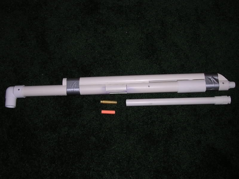
The assembled portion (ignore the duct tape, I used it to hold the receiver cover on because I haven't put in the screws that keep it in place yet):


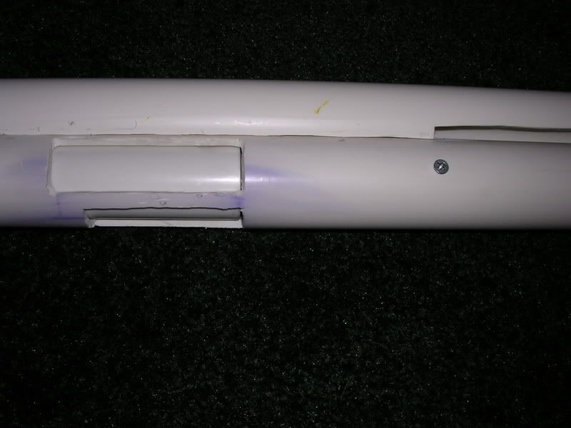
Ejection port blocked by bolt carrier in its resting position:


The magazine tube so far (I have to add some guide rails inside, but this is basically how it should look):


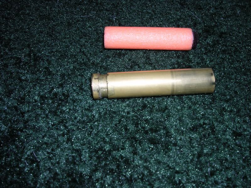
13x63mm shell with a compact CDTS in the background:


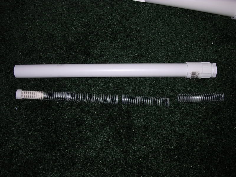
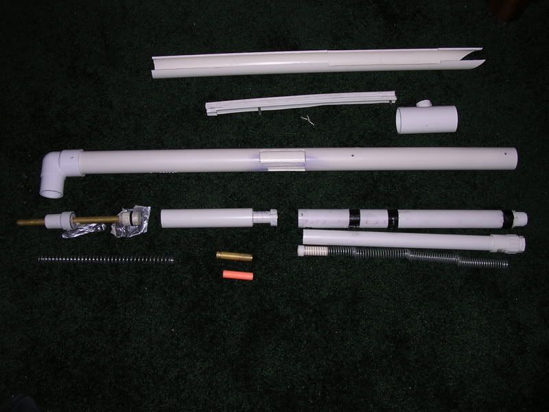
The disassembled portion that I have (the duct tape had been placed under the plunger head to protect the carpet from the silicone lubricant, it does not serve any other purpose. Also note that the spring perch has been left in the end of the PVC elbow that serves as part of the stock. I didn't take it out becase the elbow is a pain to remove.):


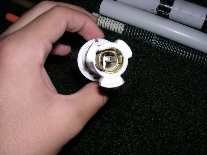
The bolt and bolt carrier (this component has been improved over boltsniper's bolt, as the bolt automatically returns to its forward position when nothing is engaging it. This prevents jams occurring as the result of the bolt rotating while disengaged from the chamber, and also guarantees that the bolt head will be oriented correctly to eject the shell every time):


The chamber with the lugs that engage the bolt head:
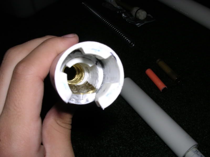


The bolt and chamber while they are locked (note the steel pins that keep all tabs in place even if the superglue and PVC cement weakens or fails):
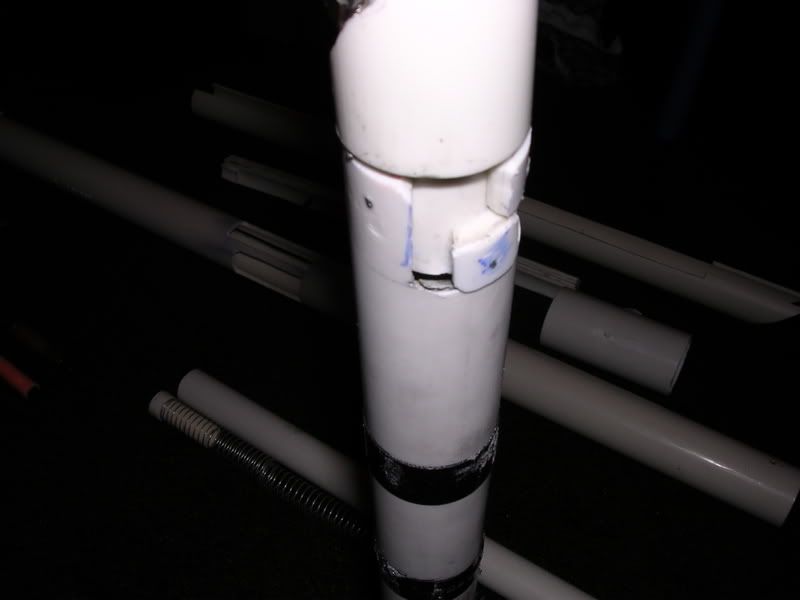


That's about it. Questions, comments, critiques? This gun will be finished. I do not give up on projects like this.
Report Spam   Logged

Share on Facebook Share on Twitter

General Cole
General
Level 5 Poster
*

Points: 225
Posts: 1135

Nerf On!


View Profile WWW
« Reply #1 on: September 02, 2007, 03:39:31 pm »

WOW.  And I thought the SCAR was complicated.  What do you think the material cost of this guy will be when done?
Report Spam   Logged
ShadowHunterAlpha
Level 2 Poster
*

Points: 652
Posts: 83


Shadow Militia Spec. Ops. and Commander-in-Chief.


View Profile
« Reply #2 on: September 02, 2007, 07:51:51 pm »

WOW.  And I thought the SCAR was complicated.  What do you think the material cost of this guy will be when done?
The FAR, SCAR-N, and SCS-N "Phantom" (this gun) are not really based on complex ideas. What it comes down to is the tools at your disposal. If you have a machine shop like boltsniper and CS, then you're fine. If you have only a Dremel, like me, it gets a little bit more complex, but is still possible to do this. Seeing as I just got a mini-lathe for my birthday, it gets easier (I only wish I had had it when I began, because everything I would have had to use it for is basically done now). The things that make it seem complex are the magazine/carrier, bolt, and shells. Of course, this is my own speculation, but then again someone who has more experience with this sort of thing is bound to see it as easier. This was to be my first homemade, and I had no solid plans, but my vision served as the blueprints. I didn't put this thing to paper or program, and I'm not sure that it would have made it any easier anyway. I hate planning. I tinker until it works.

As for the cost: I would imagine the raw materials cost below $40. What may drive it over is the brass, and the springs, but CPVC, PVC, and (thin) steel rod are dirt cheap.
Report Spam   Logged
General Cole
General
Level 5 Poster
*

Points: 225
Posts: 1135

Nerf On!


View Profile WWW
« Reply #3 on: September 02, 2007, 07:56:38 pm »

Thanks.  I can just never figure out the whole reciever thing with the brass and PVC that locks into itself.
Report Spam   Logged
ShadowHunterAlpha
Level 2 Poster
*

Points: 652
Posts: 83


Shadow Militia Spec. Ops. and Commander-in-Chief.


View Profile
« Reply #4 on: September 02, 2007, 08:09:54 pm »

Thanks.  I can just never figure out the whole reciever thing with the brass and PVC that locks into itself.
The bolt only rotates because there are two pieces that make it up. The bolt carrier is the thick 1" I.D. PVC tube with a small portion of a 3/4" PVC pipe at one end. The 3/4" pipe has been bored out to fit the 1/2" PVC that is the bolt itself. This small (about 2.25" in length) piece is free to slide back and forth in the widened 3/4" PVC. What makes it rotate is a small, slanted track cut into the 1" and 3/4" pipe. It is not perpendicular or parellel to the front of the bolt carrier, but about 40 degrees angled from a line that is perpendicular. A pin that is driven into the bolt and then run through this track ensures that when the bolt head encounters resistance, it will be forced back into this track. The pin, called a cam pin, rides in the groove and makes the bolt follow its path.

Basically, it is a free-sliding portion of 1/2" PVC that slides in another pipe and is kept aligned by a cam pin in a track. Picture 7 shows the setup of the brass, but it is kind of vague. I will try to post a better-focused one later.
Report Spam   Logged
General Cole
General
Level 5 Poster
*

Points: 225
Posts: 1135

Nerf On!


View Profile WWW
« Reply #5 on: September 03, 2007, 04:43:16 pm »

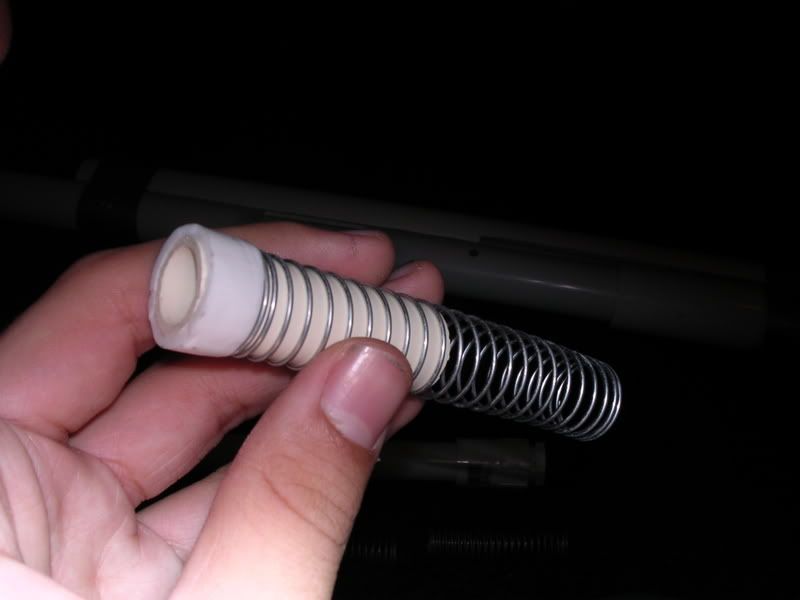
Its cool, hi-res comps rule.  I can see it.  I assume that that is the Shell ejector?  Or is that the section that locks the shell in place?
Report Spam   Logged
ShadowHunterAlpha
Level 2 Poster
*

Points: 652
Posts: 83


Shadow Militia Spec. Ops. and Commander-in-Chief.


View Profile
« Reply #6 on: September 03, 2007, 05:09:40 pm »

It's the ejector. The silver tube-like fixture behind it is a full-length pen spring that was abnormally strong. The ejector iteslf is locked into the brass ring, or shell seat, by a small nub of material superglued onto it.

--------------------------------
=========================
............................=----
..............................----
..............................----
..............................----.......--
--------------------------------
This is a quick cut-away illustration. (----) represents the outer brass casing of the ejector/extractor assembly and the shell seat. It is retained with a pin that can be tapped out for quick field stripping. (===) represents the ejector. The nub that retains it is shown as the single symbol in the third row. (...) represents open space. The (--) symbol on the second-to-last row is the ejector claw that catches the rim of the shell.
Report Spam   Logged
General Cole
General
Level 5 Poster
*

Points: 225
Posts: 1135

Nerf On!


View Profile WWW
« Reply #7 on: September 07, 2007, 06:51:18 am »

Oh.  Awsome.  I get it now, thanks!
Report Spam   Logged

Pages: [1]
  Print  
 
Jump to:  

This site has been created by Jonas R. Wasilco.
Some fourm elements have been inspired by C:DOS Abandonware.

Like this fourm? Get your own!

Bookmark this site! | Upgrade This Forum
SMF For Free - Create your own Forum


Powered by SMF | SMF © 2016, Simple Machines
Privacy Policy