Nagants Mav: v1.1
A Study in Failure
CAUTION: This mod is, currently, a failure.Okay, now that weve (hopefully) taken care of the skimmers, lets move on
Yep, you read that right. I had an idea, I tried it out, and (so far, at least) it has resulted in failure. I am, however, posting it here because I believe it is deserving of further thought. Perhaps someone will be able to make a suggestion of how to make it work; however, if not, then at least it may provide inspiration for other, similar modifications on the Maverick and/or other turreted blasters
even though, as you will see, the Maverick has a unique feature that makes it ideal for this modification.
BackgroundSome time ago, when I was naught but a noob who was reading every topic on the Nerf forums that I could, I came across a post by Lemmypoo, here at the Haven. In a discussion about ways to mod the Mav, he referenced the 1895 Nagant Revolver. This rather strange revolver had a cylinder that not only rotated but also moved forward to seal with the barrel. This was meant to prevent the escape of gases and thus improve power and efficiency.
Additionally, Captain Slug created the Front-End Swappable Clip mod; completing this modification led to the inspiration of how to recreate the Nagant action in the Maverick.
When I began my work on the Viper, which was to be a semi-automatic (or, more accurately, double-action) pistol utilizing two solenoid valves, I started with Slugs front-end swappable clip mod. Once accomplished, I realized that with the cylinder now affixed to the rotation mechanism I could pull back the cylinder slightly by pushing the button that normally releases the cylinder to swing out.
The ModAs most modifications begin, we must begin with opening the Mav. I leave it to my audience to figure out how to do that.
While youre at it, take everything out of the shell. You can probably leave the slide return spring and the trigger return spring, but everything else must go.
The true modding begins with a fair amount of dremeling. The first things to remove are two support posts that would be in our way later if we dont remove them. See the following picture for their location; there is one on the left-hand half of the shell, and another on the right-hand half of the shell:
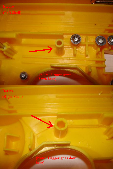
Next, you have to remove several parts of the front face of the Mavs body. See the next pictures for the best descriptions.
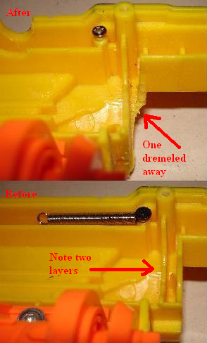
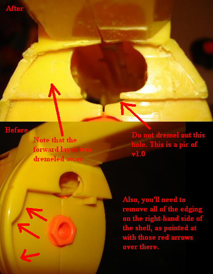
Basically, youre going to be increasing the gap between the back of the cylinder/turret, and where the air exits the main body of the Mav. Thats right, I said increasing it. Were going to increase it, in order to decrease it.
I dont want to spoil the surprise, but here is what were aiming for:
If youre still interested, lets continue with the modification; but, first, youre going to have to completely disassemble your turret. Dont leave a single screw undone, and you can throw all of the air restricting (AR) pieces away. The ARs: you will not need them. Ill again leave those steps up to the audience to figure out on their own, since theyre fairly simple.
Heres a picture of the cylinder mods:
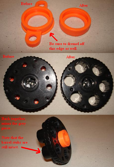
Take the orange ring seen in the first picture and dremel both the wings and the outer edging off such that the outside is just a smooth ring. Also, drill/dremel out the back of the turret. If this modification works, this will allow the turret to be loaded from the rear without compromising the seal (due to later modifications to that effect). When you reassemble the rear portion of the turret, youll leave the grey piece out and it will look like the last picture.
Next, we need to start working on the rotation mechanism:
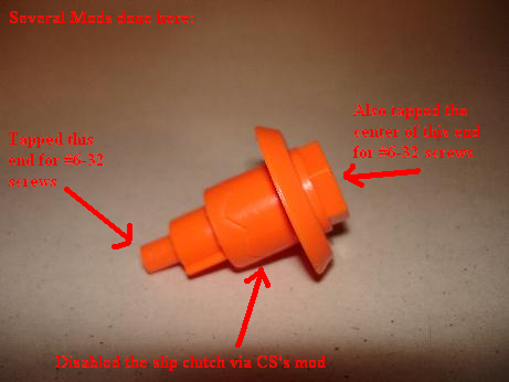
Like Captain Slugs updated End-Clip mod, tap the center of the front of that piece. According to Slug: drill the center of this part with a 7/64th-inch bit then tap it for UNC #6-32. Also, I did Slugs mod to disable the slip clutch (seen in his Drop Clip mod). Also, thread the opposite end. This back end is actually already threaded to hold a screw when stock, but we need to be able to put a spindle in there:
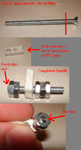
Take a #6-32 screw and cut it at the red line shown above. I had the exact length of the cut screw written down, but I lost the paper. Also, make a piece like that white one. I cut it from a piece of 2 PVC, if I remember correctly, so it is fairly flat. All of those nuts act as spacers, as well as keep each other from spinning off during use. I tightened them against each other using two pairs of pliers, causing them to bind up. They wont come off the screw unless you put a fair amount of force on them in opposite directions. Also, dont forget to cut a small slot in the end of the screw. This will allow the use of a flat-head screwdriver.
Now to do a few other mods:
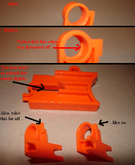
Dremel out the hole in the rear support slightly, so that you can fit the nuts on the spindle through there; it should be slightly loose, so that you can freely spin the spindle. Also, you may need to extend the notch on the trigger in the forward direction slightly. Finally, turn the rear support upside down and dremel off a small tab. This allows the armature that connects to the trigger (and causes the turret to spin as you pull the trigger) to come back further.
Now, you can reassemble the rotation mechanism:
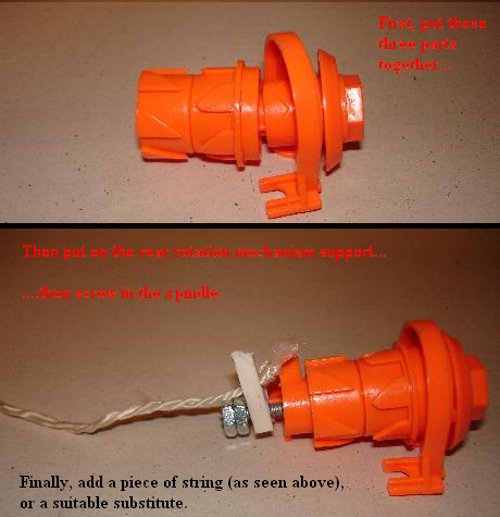
Put the forward support on, followed by the ratcheting drum thing and the spring. I actually replaced the spring with something that was a little weaker, as it is hard to pull the trigger with the (fairly powerful) stock spring. Next put the rear support on and then screw the spindle into the rear of the rotation mechanism. Finally, attach a string or something to the plastic piece. After that, you can screw the rotation mechanism back into the shell and put the two halves of the shell together.
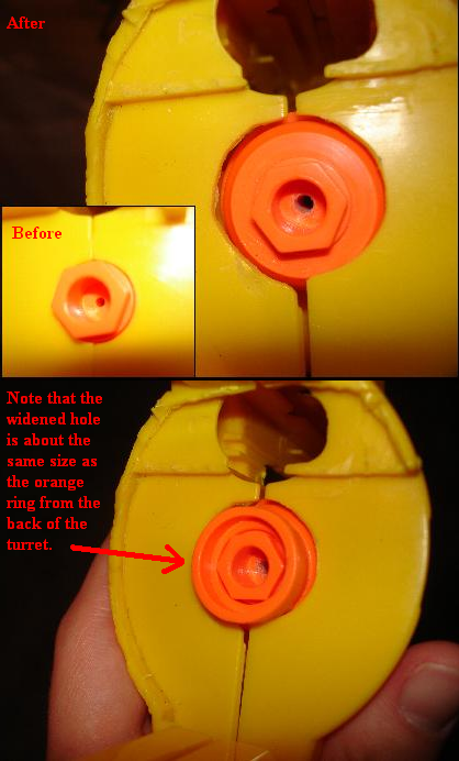
Before attaching the turret, take the two orange parts from the back end of the turret. Place them on the hexagonal part sticking out of the front of the shell. Using the ring that we modified earlier as a template, widen the hole around the hexagonal piece:
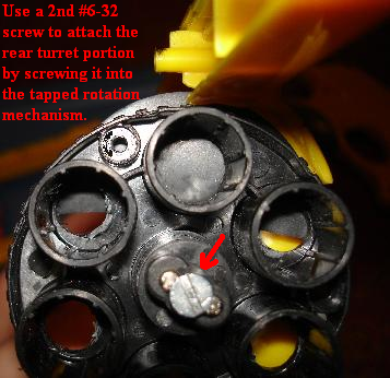
Now, you can use a second #6-32 screw to attach the rear end of the turret:
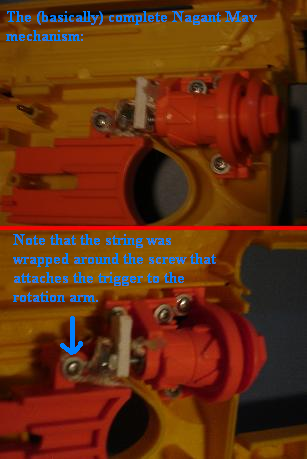
And heres how the internals should look when you are all done (note the bit about attaching the string to the trigger):
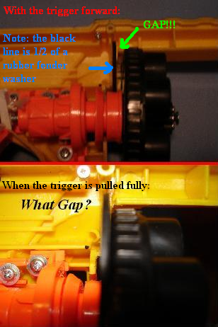
And, heres how it works, summarized in two pictures:
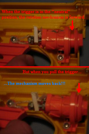
When that mechanism moves back, it pulls the turret back as well, allowing an interface between the air output and the rear of the cylinder. All that stuff that we dremeled off the front of the shell allows the turret to move back.
Now the bad news: I tried to simply modify the stock air delivery system, but I couldnt get it to work. Problems were:
1. I couldnt shape the rubber washer quite right to fit around the nozzle of the plunger chamber. Thus, the seal was far less than perfect when the cylinder moved backwards. The problem is that the front end of the plunger sticks out from the surface of the body.
2. One word: timing. Firstly, the turret must first rotate then be pulled back. Additionally, this all has to happen before the plunger is released. Its a nightmare.
3. When the cylinder is pulled back, the whole thing tends to bend in one way or another (cant remember right now, and its at home)
Possible solutions:
1. I dont know, try something different? I got what appeared to be a very good seal before installing the plunger, so maybe if I just remove that, itll be fine.
2. It would make every thing much easier if I could separate the rotation and/or backwards movement from the actual firing. I have ideas, but they all open up a whole new can of worms.
3. Some sort of plate could be used to build up the majority of the front face to the same level as where the air output is. This ones actually pretty easy to solve, as long as one has something that is flat and of the correct thickness.
It should be noted that, like Slugs Front-end clip mod, the barrels on this can be extended if you cut off the front part of the frame. In fact, you could simply extend the frame to make room for the extended barrels.
Speaking of which, the barrels should be nested inside the back of the turret if one wishes it to be rear-loading. I find that 17/32 brass fits just slightly loosely, and OMCs PETG, 9/16 brass, and CPVC could conceivably be made to fit with some work.
Of course, longer barrels will be useless without some sort of integration.
Hope you enjoyed the writeup, and any and all ideas are of course welcome.


